







-
1–3 days expedited prototype manufacturing & flexible, responsive supply chain fulfillment
-
Firm commitment to on-time shipment and consistent premium product quality
-
Comprehensive material options + full range of industrial standard surface finishing treatments
-
Factory-direct quotation & fully open, transparent cost breakdown
-
Quality system certified to ISO 9001:2015 / IATF 16949:2016 standards
-
Turnkey integrated assembly service: We supply complete finished usable goods and standalone spare parts
One-stop Custom Metal Service From Prototyping to Mass Production
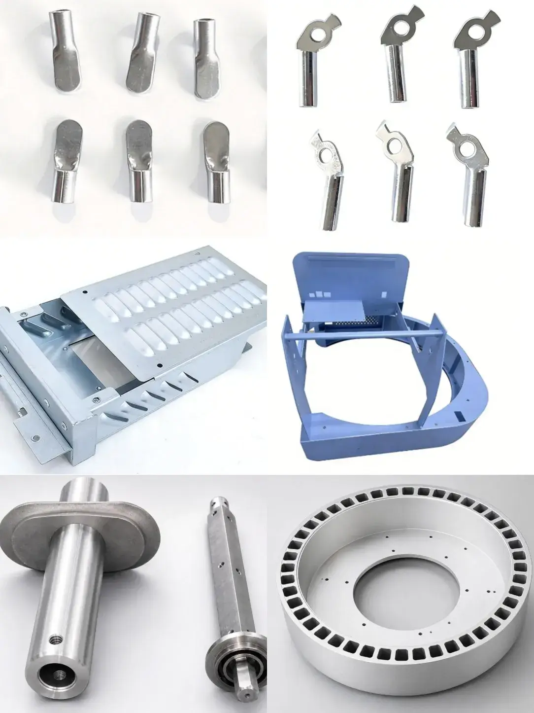
support diverse engineering and manufacturing applications.
-
Competitive Prices & DFM
-
24/7 Engineering Support
-
Quick Turn, Short Lead Time, not MOQ
Verify Certifications On Demand: IS0 9001:2015|IATF 16949:2016

about chuangkai
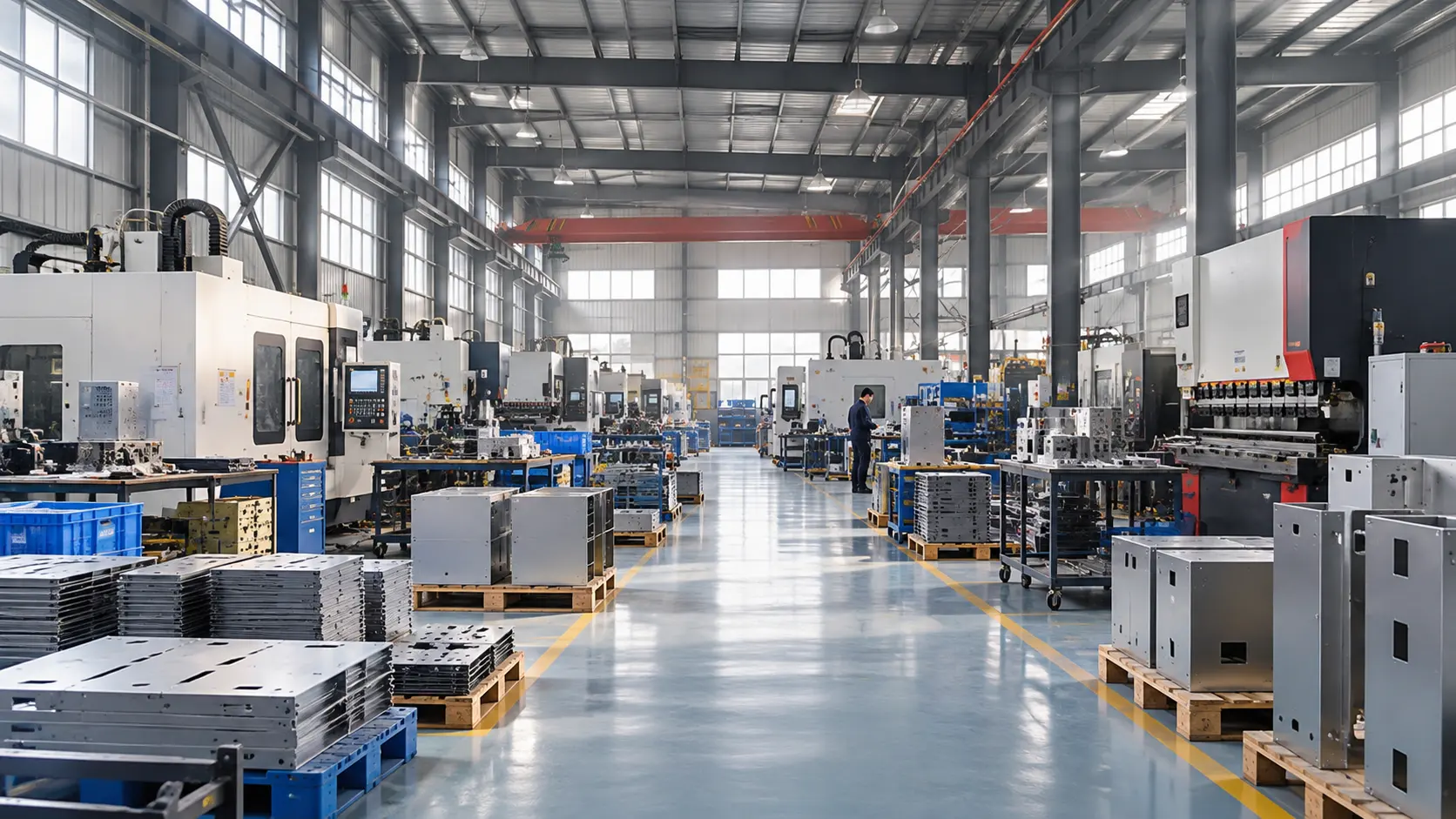
Zhejiang Chuangkai Mechanical and Electrical Technology Co., Ltd. was established in March 2003, with a registered capital of 15 million RMB. The company is a high-tech enterprise integrating the design and manufacturing of precision tooling, precision metal stamping, precision sheet metal processing, precision machining, surface painting, powder coating, and assembly of precision components.Currently, it has 95 employees and possesses advanced precision processing equipment and standardized workshops, with a total area of approximately 13,500 square meters. We have obtained ISO9001, IATF16949,ISO45001, ISO14001 system certifications.

Precision stamping tooling design & manufacture

Main stamping equipment in the stamping workshop: 18 sets of high-speed precision punch presses with specifications such as 16 tons, 25 tons, 40 tons, 60 tons, 80 tons, 110 tons, 200 tons and 250 tons. The speed of the precision high-speed punch press can reach 500 times per minute.
Materials for stamping processing: brass, phosphor bronze, beryllium bronze, nickel white copper, as well as various types of steel and stainless steel materials, Ni strips, cold-rolled steel, strip steel (including pre-plated), galvanized sheets, low-carbon steel, spring steel, and other composite materials.
Precision sheet metal manufacture

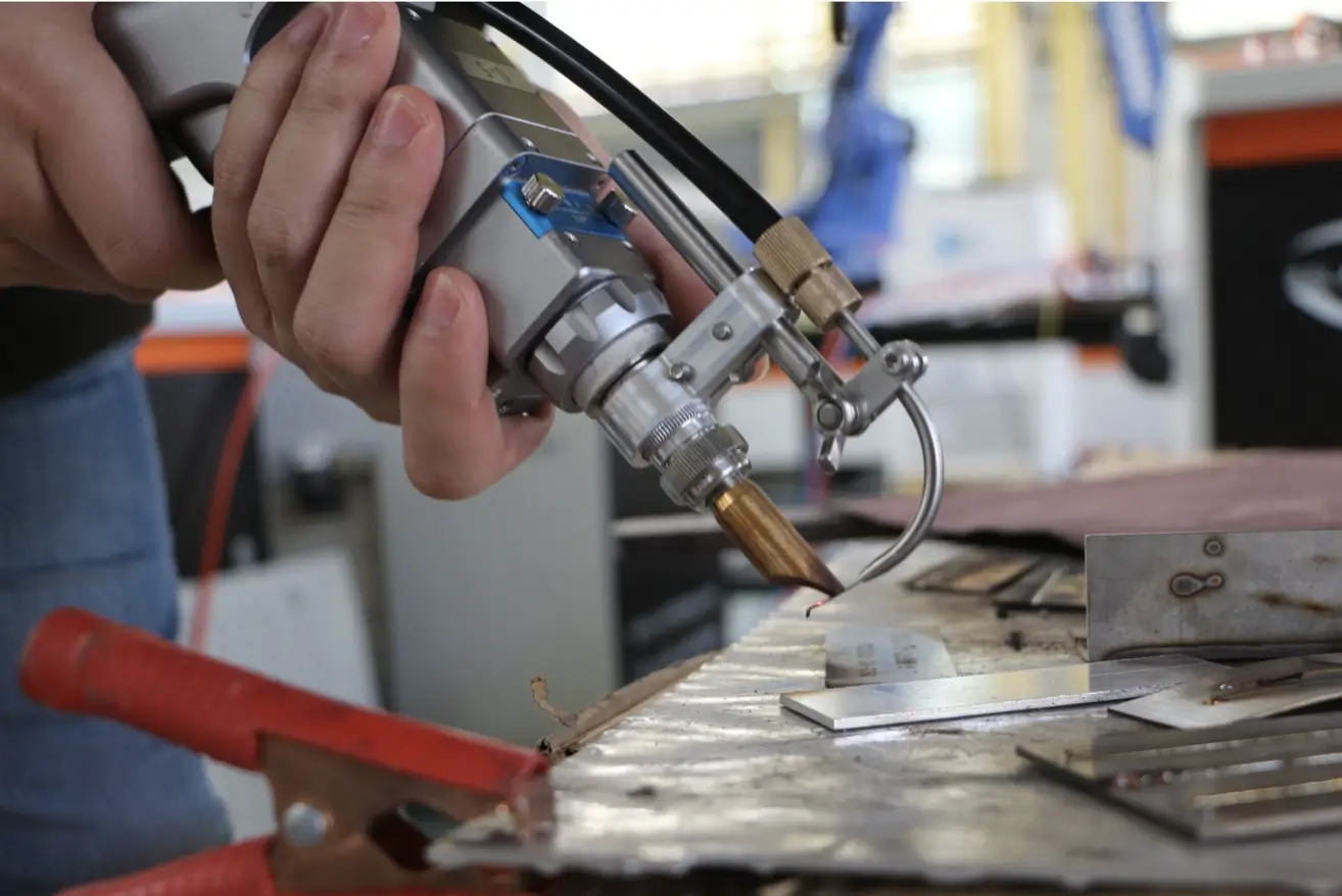
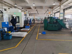
The sheet metal workshop is equipped with precision sheet metal processing equipment, including 2 large-scale advanced CNC laser cutting machines, 1 CNC punch press, 5 CNC bending machines, as well as riveting machines, welding machines, grinders, wire drawing machines and other equipment.
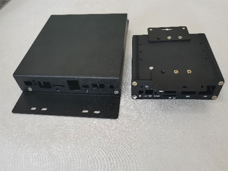
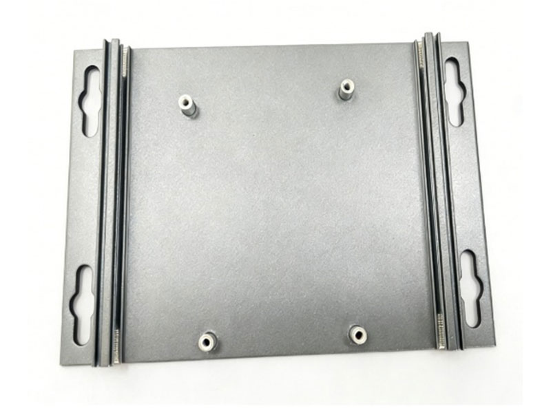
The processed products cover industrial automation, medical equipment, electrical equipment, electrical boxes, electrical junction boxes and other fields. It can perform precision processing such as rapid cutting and sheet metal processing on the following metal materials: stainless steel, carbon steel, silicon steel, aluminum alloy, galvanized sheet, aluminum-zinc plated sheet, etc.
Powder Coating & Painting

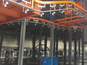
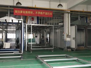
One automatic powder coating line;
One manual powder coating line (for large parts and large boxes);
One manual painting line (for large parts and large boxes);
One automatic powder coating and painting hybrid line under construction.
Precision machining

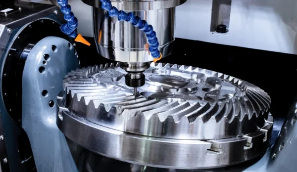
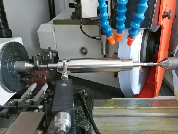
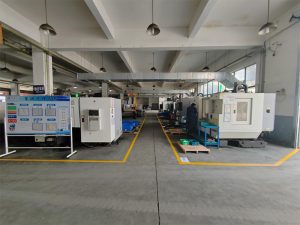
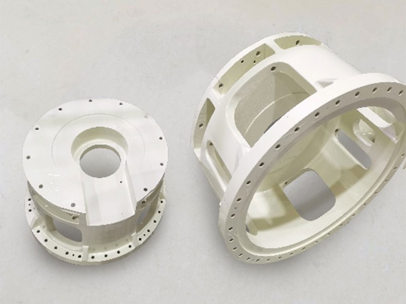
The machining workshop is equipped with precision equipment, including 6 sets of 4-axis CNC machines, 1 set of 5-axis swiss-type lathe, 13 sets of precision CNC lathes, 4 sets of CNC milling machines, 16 sets of Taiwan Mingyang precision automatic lathes, as well as precision ordinary lathes, precision 3-axis digital display milling machines, precision bench lathes, Taiwan Jizuan automatic edge milling machines, precision thread rolling machines, thread rolling dies, precision tapping machines, precision drilling machines, precision Taiwan digital display milling machines, precision knife grinders, internal and external cylindrical grinders, centerless grinders, sawing machines, ultrasonic cleaning and drying machines, polishing machines, electric welders, arc welders and other equipment.
our
Intro video
our fun facts
No more coordinating 5 + suppliers. Cost - Smart Production : Vertical integration + process optimization = 15 - 30% cost reduction vs. fragmented supply chains.
Speed-to-Market:Concurrent engineering cuts lead times by 40%. Meet deadlines without compromising quality.
Request a Free DFM Analysis:Upload your drawings/samples. Our engineers will identify cost & efficiency optimizations within 48 hours.

the company is built
0
registered capital
0M
staff
0+
factory area
0+
our case
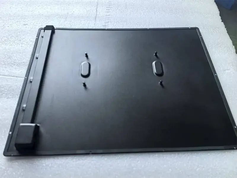
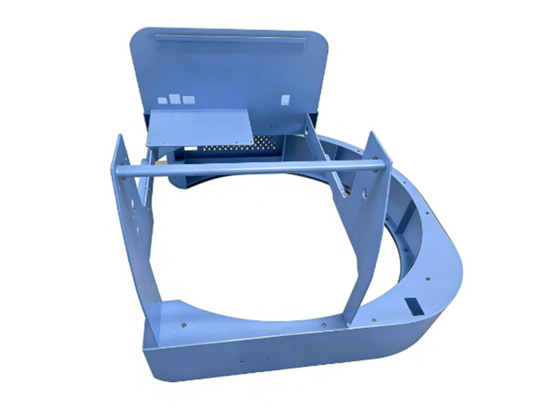
Use Stretching process Substitute for Weld+Polish +Scrape putty Technology
Use Stretching process Substitute for Weld+Polish +Scrape putty Technology
Break through the technical bottleneck and create high-quality and price-price metal structural parts for teaching demonstration equipment:
When a customer was developing a large demonstration computer for training and teaching, its core metal structural parts encountered serious challenges. The initial design of the part uses the welding process to make the protruding part, but in the product testing stage, the poor welding tightness makes the product unable to pass the key test. At the same time, the high cost of the welding process makes the price of the parts significantly higher than that of competitors, the project delivery is imminent, and customers face great pressure of quality and cost.
Accurately locate pain points and respond quickly to tackle them:
After understanding the customer’s plight, we quickly set up a special technical team. In the first technical seminar, we deeply analyzed the root cause of poor welding airtightness. Although by optimizing welding parameters and introducing welding machinesPeople, we have successfully solved the problem of airtightness and met the initial quality requirements of customers, but the problem of high welding cost is still pending.
Innovative plan, two-proged:
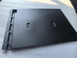
The technical team didn’t stop there. After many rounds of internal discussion and close communication with customers, we have proposed a fundamental solution: replace the original welding with an integrated stamping and stretching process.+Polish+Scrape putty Craft. This not only completely eliminates the risk of welding tightness from the source, but also significantly reduces the production cost and provides the possibility for the product to win a larger market space.
Seize”Impossible”, fulfill the promise:
Customer feedback has considered stamping.StretchingThe plan, but other suppliers said it could not be realized. In the face of questioning, we firmly believe that”One learns by doing”. Based on the profound accumulation of technology, we provide customers with key optimization suggestions, including:
Adjust the tensile slope angle to optimize the material fluidity, and choose a specific brand of cold-rolled steel plate with better tensile performance.
Excellent results, praised by customers:
After the plan was determined, we conducted multiple rounds of rigorous process tests and sample verification. The final delivered parts perfectly meet the customer’s design requirements and performance standards. The customer was extremely satisfied with the results, and not only gave high praise:”This is the perfect product in my ideal design!”He also expressed his sincere thanks for the ability of the Chuangkai team to overcome difficult problems. We have successfully helped customers within the urgent delivery period, while solving difficult quality and cost problems, and helping their products gain an advantage in market competition.
OvercomiNg Technical Hurdles to Deliver High-Quality, Cost-Effective Metal Components for Educational Displa And Systems
The challenge:
A client developing large demonstration computers for training and education faced Critical iss Ues with a key metal structural component. The initial design utilized welded protrusions. However, during product testing, poor weld sealing integrity caused failures. Compounding the problem, the high cost of the welding process made their component signIficantly more expensive than competitors’. With project deadlines looming, the client was under immense pressure to resolve both quality and co St challenges.
Our Rapid Response & Initial Solution:
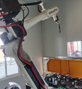
Upon learning of the client’s dilemma, we imMediately formed a dedicated technical task force. In the initial technical review, we thoroughly analyzed the root cause of the sealing failure. Through extensive welding parameter optimization trials and the strategic implementation of roboticWelding, we successfully achieved the required sealing integrity, meeting the client’s quality speci Fications.
Identifying the Deeper Issue & Proposing Innovation:
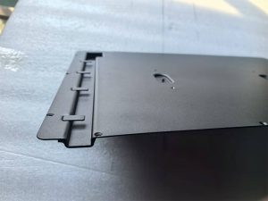
While the immediate sealing issue was resolved, the fundamental problem of prohibitive manufacturing Costs remained. Refusing to settle, our task force engaged in intensive internal brainstorming and maintained close Communication with the client. We proposed a transformative solution: replace the welded assembly with a single-piece component foRmed by stamping and deep drawing.This approach promised to:
- Eliminate the root cause of sealing failures inherent in welding.
- Achieve significant cost reduction By streamlining production.
- EnHance market competitiveness** for the client’s end product.
Breaking Through the “Impossible”:
The client revealed they had previously explored stamping, but other suppliers deemed it unfeasible For this part. Guided by our belief that”Proof lies in practice,” we leveraged our technical expertise to propose crucial design optimizati Ons:
- 1Adjusting the draw angle to improve material flow.
- 2Specifying a higher-grade cold-rolled steel with superior deep-drawing properties.
The Successful Outcome:
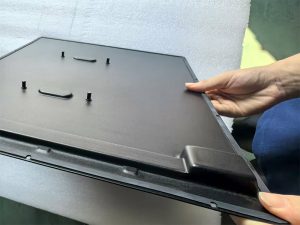
After rigorous prototyping and validation testing based on our optimizeD design, we delivered the final component. The results were exceptional, perfectly aligning with the client’s design intent and performance req Uirements.The client expressed deep satisfaction, offering high praise: “This is the perfect product I en Visioned in my design!” They explicitly thanked ChuangKai for solving their persistent technical headache. We enabled the client to meet their critical deadLine while simultaneously overcoming both the quality defect and the cost barrier, significantly enh AnCing their products’s market competitiveness.
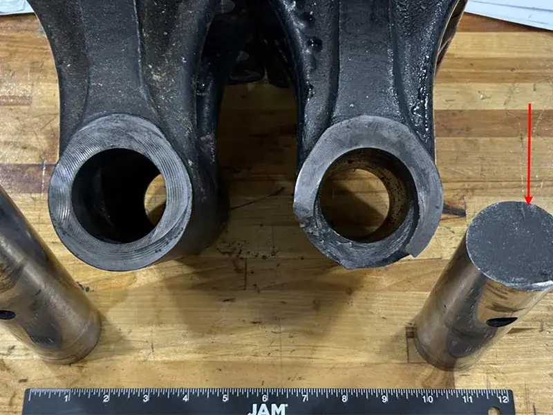
Case Study on Improvements for Agricultural Machinery Shaft Breakage
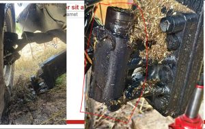
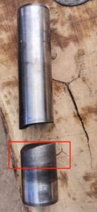
In July 2024, a customer gave feedback that Theirs The axis of the combine harvester There was a rupture during the field operation, and the end customers were very anxious about the fact that the ripe grain could not be harvested smoothly. They initially thought that it might be the raw material of the shaft 40CrNiMoA or the heat treatment process that did not meet the requirements. We have received Their help the broken axis was analyzed at the first time, and it was concluded that it was not Raw materials and There is a problem with the process, but it is designed by the customer.SeasonIt is not taken into account the complex working conditions of the equipment.And one-way force fatigue Hidden dangers, customer requirements Whole Tall Hard Degree heat treatment leads to the high hardness of the core, which is easy to produce Tired Break,After analysis We suggest adopting Whole Adjust the quality plus Surface The process of induction quenching replaces the original heat treatment Overall high hardness The process makes the core Hardness Reduce And the outer surface hardness is high, which meets the wear resistance., and sent it to the customer according to the suggested process.The new sample achieved excellence in the second field experiment.Bear fruit The feedback of.
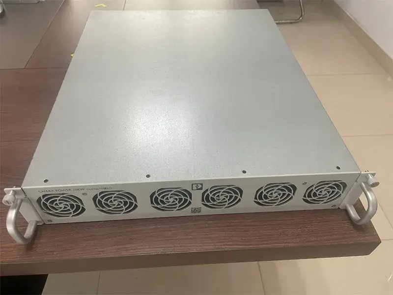
Power supply box enclosure improvement process
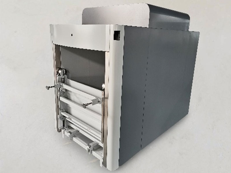
A German customer of our company has a combination box that has difficulty in the design stage. If the riveting method is adopted, it will protrude from the plane to affect the function. If the welding method is used, the appearance does not meet the requirements and the cost is high. After contacting us, we happened to have successful cases in other projects. We can solve customer problems very well by using double flat head rivets and salad holes. We sent samples to customers.
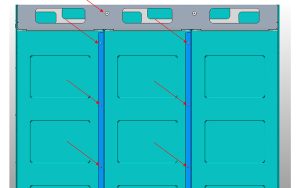
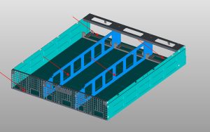
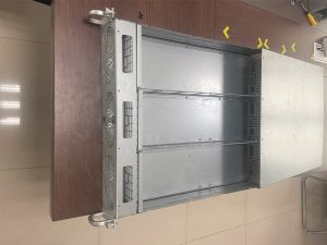
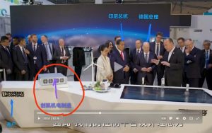
They were very satisfied and achieved rich results at the Hanover exhibition.,AchieveUnanimous praise!

Your End-to-End Manufacturing Solution Partner
Your End-to-End Manufacturing Solution Partner
From Concept to Completion – Precision Engineered for Global Success
At ChuangKai, we eliminate the complexities of multi-vendor sourcing. As a vertically integrated manufacturer specializing in ODM & OEM solutions, we deliver seamless production of high-precision components through our comprehensive capabilities:
Integrated Manufacturing Services:
- Machining: CNC Milling/Turning, Swiss Machining
- Metal Fabrication:Laser Cutting, Bending, Welding
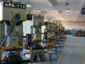
- Stamping & Forming: Progressive Die Stamping, Deep Drawing
- Tooling & Molding:Custom Die/Mold Design & Manufacturing
- Surface Treatment: Powder Coating, Spray Painting
- Assembly & Testing:Full Kitting, Quality Validation
ODM/OEM Advantages for Your Business:
Design Innovation
Our engineering team collaborates with you to optimize designs for manufacturability, cost-efficiency, and performance – transforming concepts into market-ready products.
Single-Source Accountability
No more coordinating 5+ suppliers. We manage the entire workflow under one roof:
Design → Prototyping → Tooling → Raw Material Sourcing → Production → Finishing → Assembly → Logistics
Cost-Smart Production
Vertical integration + process optimization = 15-30% cost reduction vs. fragmented supply chains.
| Speed-to-Market |
Concurrent engineering cuts lead times by 40%. Meet deadlines without compromising quality.
| Quality Built-In |
ISO-certified processes with digital traceability. PPAP, FAIR, and CPK reporting available.
√ Industries We Serve:
Automotive | Industrial Machinery | Medical Devices | Renewable Energy | Robotics | nuclear electricity generation
Why Global Clients Choose Us:
Problem Solvers:Like the [Teaching Demonstration Equipment Case] where we replaced welded assemblies with integrated stamped parts –solving leaks + cutting costs 25%.
Scalable Capacity:Support from NPI prototypes to 1M+ unit production runs.
Technical Agility: 20+ engineers ready to tackle complex GD&T, tight-tolerance (±0.01mm), and material challenges.
→ Request a Free DFM Analysis
Upload your drawings/samples. Our engineers will identify cost & efficiency optimizations within 48 hours.
Products

FAQ
This section answers common questions about our mechanical and electrical products, services, and policies. It helps you quickly find information without contacting support
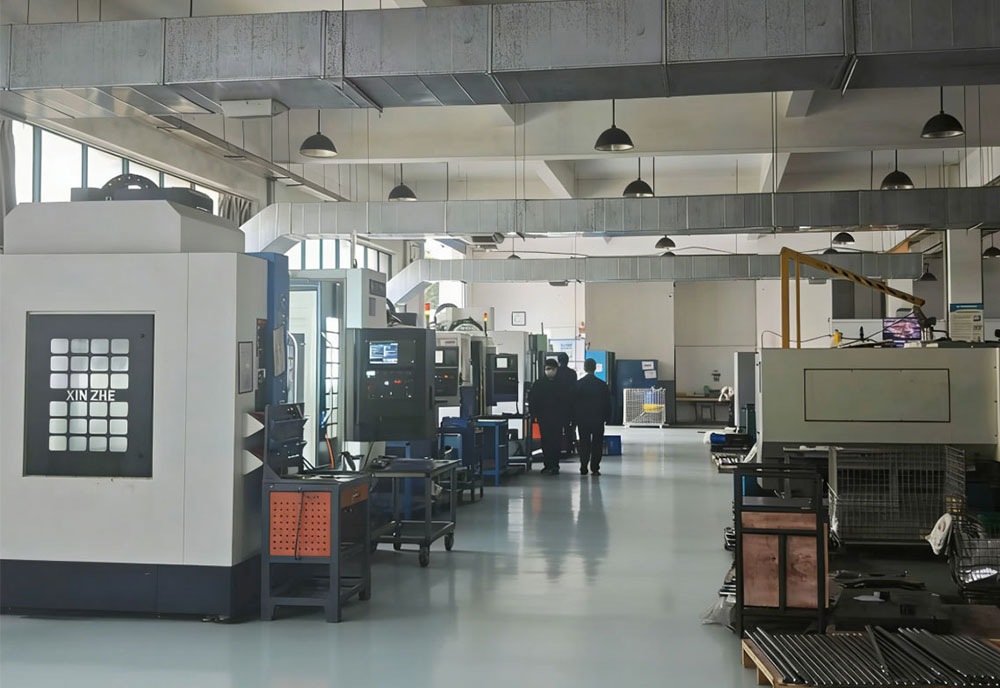
Our core strength lies in integrating the entire industrial chain, from precision machining, precision sheet metal processing, stamping production, tolling design and manufacturing, professional surface treatment by spraying to final product assembly, and implementing an outstanding quality management system throughout the entire process. This means that customers do not need to coordinate multiple suppliers to obtain efficient, coordinated, and consistent services. Our strict quality control is implemented in every link, ensuring that what is ultimately delivered is not only parts or products that meet requirements, but also stable, reliable, and high-standard overall solutions, effectively helping customers shorten delivery times, reduce costs, and improve supply chain efficiency.
Customized non-standard component processing. This depends on the complexity of the product. The general delivery period is usually between 2 and 4 weeks.
25
Years Experience



















Contact us
recent articles
recent articles
Need mechanical and electrical solutions or have questions? Get in touch!
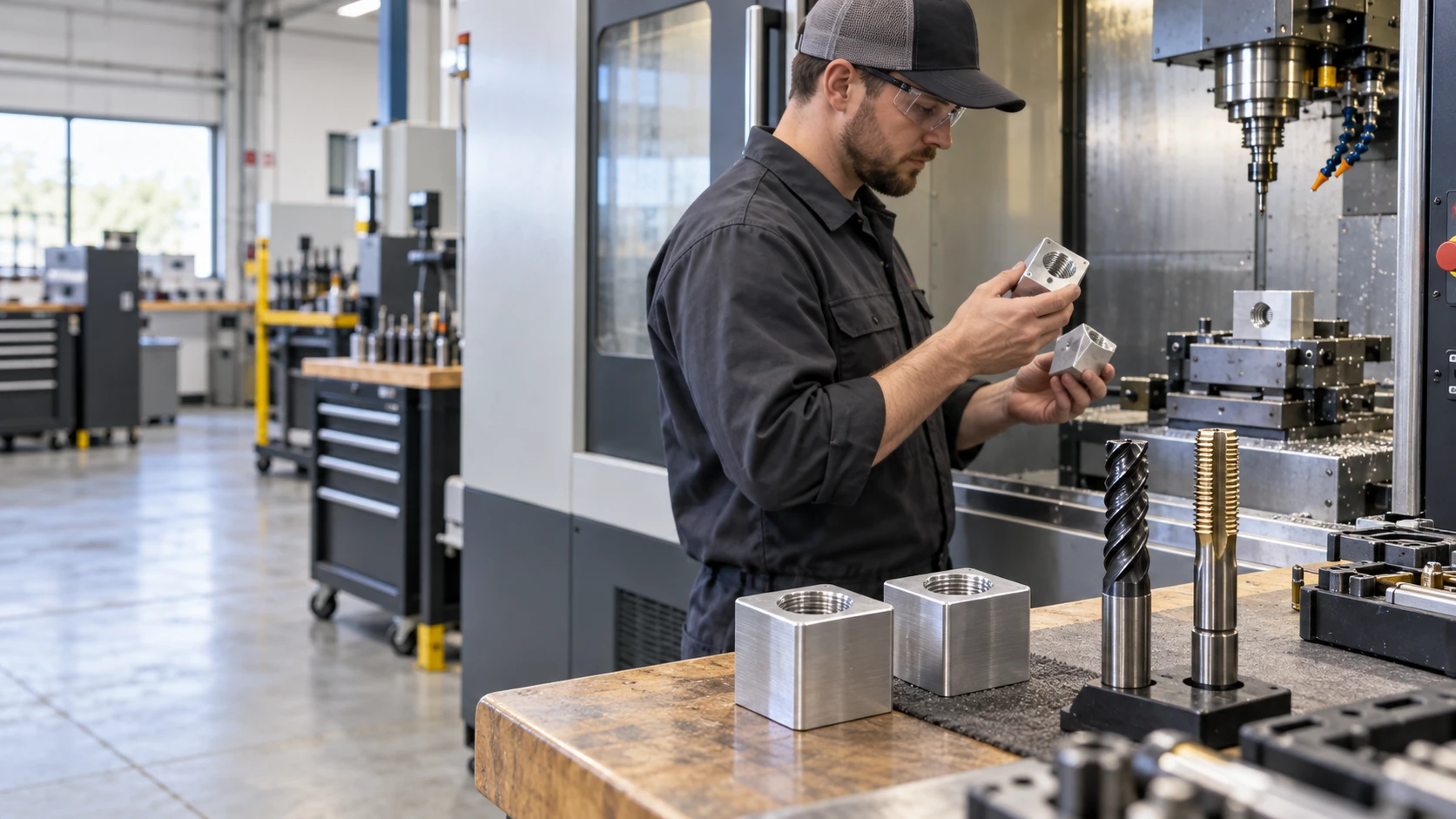
Tapping vs. Thread Milling for CNC-Machined OEM Parts: Choosing the Right Internal Thread Process
23
October
The choice between tapping and thread milling depends on the hole, material, thread specification, production quantity, machine capability, and cost of failure. Tapping is usually the faster route for repeat production of standard internal threads. Thread milling offers more control over thread size and fit, handles a wider range of diameters with fewer tools, and can reduce the consequence of a tool failure in a valuable part.
Neither process is universally better. A through-hole in a stable aluminum part may favor tapping, while a large thread, difficult material, expensive near-finished component, or close fit adjustment may justify thread milling. Blind-hole geometry and usable thread depth can change the answer again.
Tapping vs Thread Milling at a Glance
| Decision factor | Tapping | Thread milling |
| Cycle time | Often faster for standard repeated threads. | Usually longer because the tool follows a helical path. |
| Tool flexibility | One tap normally matches a specific size, pitch, and form. | One cutter may cover multiple diameters that share a compatible pitch and profile. |
| Fit adjustment | Limited after the tap and hole preparation are selected. | Tool-path offsets can adjust the finished thread within process limits. |
| Failure risk | A broken tap may be difficult to remove from the part. | A smaller cutter may be easier to recover from, but breakage can still damage the feature. |
| Machine need | Requires controlled feed and rotation appropriate to the tapping method. | Requires CNC helical interpolation, suitable control, rigidity, and access. |
How Each Process Cuts an Internal Thread
Both methods begin with a prepared hole, but their tool engagement is different. The drawing must specify the finished thread; the process planner then selects the pre-hole, tool, cutting data, and inspection route.
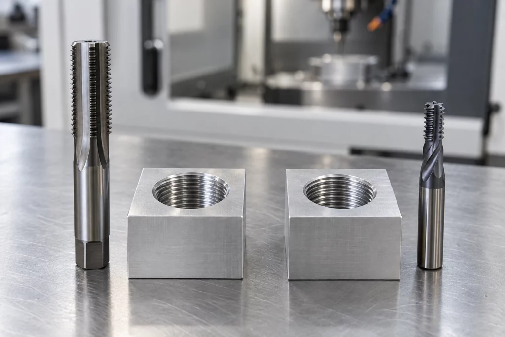
Tapping
A tap advances axially while its cutting edges or forming lobes create the complete thread profile. Because the tool engages around the circumference, torque, alignment, lubrication, chip control, and the prepared-hole diameter are important. Cut taps generate chips. Form taps displace suitable ductile material without chips, but they require a different hole size and should be approved for the material and specification.
Thread Milling
A thread mill rotates while the CNC moves it along a helical path. The cutter is smaller than the finished thread, so it engages a portion of the circumference at a time. The program controls diameter and direction, and suitable cutters can produce internal or external threads. The method needs enough bore access, tool clearance, machine interpolation, and stable workholding.
Choose by Hole Geometry
Through Holes
Through holes usually provide easier chip evacuation and fewer bottom-clearance constraints. For standard sizes and meaningful batch quantities, tapping often provides the most efficient cycle. A spiral-point cutting tap may push chips ahead through the opening when the material and application permit. Thread milling remains useful for large diameters, adjustable fits, mixed thread sizes, or parts where tool-breakage recovery influences the risk calculation.
Blind Holes
Blind holes need separate values for drilled depth, full thread depth, usable engagement, and bottom clearance. A tap has an incomplete lead before it produces full threads, and chips must have somewhere to go. Tap style, coolant delivery, chip evacuation, and reversal therefore matter. Thread milling can approach a shoulder with controlled axial positioning, but it still needs entry and exit clearance and cannot create usable thread beyond its programmed geometry. Do not specify “thread to bottom” without defining a manufacturable termination.
Choose by Material and Thread Specification
Material behavior affects torque, chips, tool wear, heat, and edge quality. Standard threads in machinable aluminum may favor tapping for speed, although chip packing or built-up edge still needs control. Tough stainless steels, high-temperature alloys, or expensive heat-treated parts may make the lower engagement and recovery advantages of thread milling more attractive. The supplier should confirm the exact alloy, hardness, and hole depth before choosing the route.
Thread size and form matter as much as material. Small standard threads may suit tapping, while larger diameters, special profiles, right- and left-hand variants, or adjustable fit classes can favor thread milling. A thread mill is not universal: its diameter, pitch capability, length, cutting form, and reach must match the feature.
Choose by Quantity and Cost of Failure
For a stable high-volume job, the shorter cycle of tapping can outweigh its lower flexibility. For prototypes and mixed families, thread milling may reduce the number of dedicated tools and allow diameter correction through offsets. The value of the workpiece also matters. Breaking a tap in an almost-complete housing can cost more than the saved cycle time; however, thread milling adds programming time and may use a more expensive cutter. Compare total route cost, not tool price alone.
Define the Thread Correctly on the Drawing
A process comparison cannot correct an incomplete specification. Use the same feature-based discipline applied to CNC machining tolerances, and include the following information:
- Thread standard and designation, nominal size, pitch or threads per inch, internal class or tolerance, and right- or left-hand direction.
- Through or blind condition, drilled depth, full thread depth, minimum usable engagement, entrance chamfer, and any bottom-clearance limit.
- Material grade and condition, heat treatment, coating or plating, quantity, critical datum relationships, and mating-fastener information.
- Inspection method, gauge standard, sampling level, first-article record, and any functional assembly test.
A complete CNC machining RFQ checklist also keeps model, drawing, revision, finish, and inspection assumptions consistent across bidders.
Verify the Sample and Production Route
Inspect the pre-hole as well as the finished thread. Confirm location, diameter, depth, chamfer, burr condition, and cleanliness. Use the specified GO and NO-GO gauges or another agreed method, then test the real mating fastener when assembly behavior matters. Record tool offsets and wear limits for thread milling, or torque, tap life, and chip-control checks for tapping. A first article should also confirm that coating, plating, or heat treatment does not invalidate the final fit.
Evaluate Supplier Capability Against the Part
CK Metal Tech publishes precision machining capabilities that include CNC milling, drilling, tapping, and related inspection resources. Its broader CNC machining services for precision metal parts provide the context for OEM process planning. The project review should still confirm whether tapping, thread milling, or another threading method is available and appropriate for the specific size, material, depth, tolerance, quantity, and inspection plan.
Conclusion
Use tapping when a standard internal thread, suitable material, controlled hole, and repeat quantity make cycle time the priority. Consider thread milling when fit adjustment, large or varied sizes, difficult materials, blind-hole constraints, or the cost of a trapped broken tap changes the economics. The drawing and sample plan should make the choice verifiable rather than leaving it to habit.
FAQs
Is Thread Milling Always More Accurate Than Tapping
No. Either process can make acceptable threads when the machine, tool, hole preparation, setup, and inspection suit the requirement. Thread milling offers useful diameter adjustment, but it does not replace process control.
Which Process Is Better for Blind Holes
It depends on usable depth, bottom clearance, material, chip control, thread size, and quantity. A suitable tap can be efficient; thread milling can improve control where evacuation or failure consequences are difficult.
Can One Thread Mill Cut Several Thread Sizes
Sometimes. A cutter may cover multiple diameters with a compatible pitch and profile, within its diameter and reach limits. Confirm the tool manufacturer’s range and the required thread form.
How Should an Internal Thread Be Inspected
Use the drawing’s specified gauge or measurement method and sampling plan. GO and NO-GO gauges are common, but depth, location, surface condition, and functional assembly may also require verification.
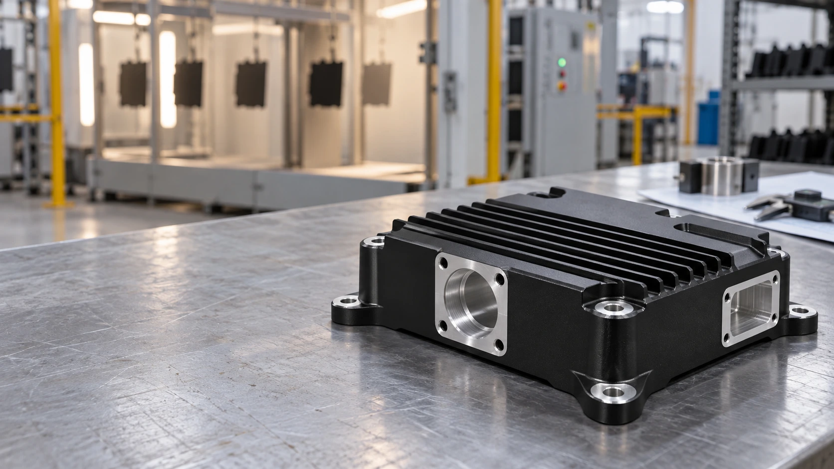
Can CNC-Machined Aluminum Housings Be Powder Coated? Thermal Interfaces, Fits, and Masking
22
October
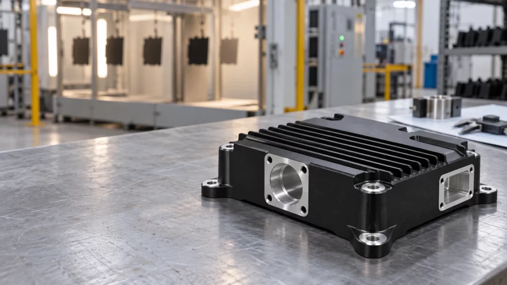
Can aluminum be powder coated after CNC machining? Yes, provided the drawing distinguishes cosmetic or protective surfaces from interfaces that must remain dimensionally, electrically, or thermally functional. A coating that performs well on an exterior wall can cause interference in a close fit, obstruct a thread, insulate a bonding point, or add thermal resistance at a heat-transfer joint.
The review should therefore start with the finished assembly, not the color. CK Metal Tech’s aluminum alloy cooling and shielding cover plate illustrates why this distinction matters: one machined component may combine an exterior cover, mounting holes, grooves, structural bosses, shielding functions, and heat-dissipation duties. Those surfaces should not automatically receive the same finish treatment.
Map Functional Surfaces Before Coating
Create a finish map on the controlled drawing or model. Identify coated faces, cosmetic faces, no-coat zones, and surfaces whose final dimensions apply after finishing. A generic note such as “powder coat black” does not tell the manufacturer how the housing must assemble or perform.
Surfaces Commonly Suitable for Coating
Exterior walls, non-mating covers, guards, and handling surfaces are typical candidates when the selected pretreatment and powder system match the aluminum alloy and service environment. Coating can support appearance and surface protection, but corrosion, chemical exposure, ultraviolet exposure, and cleaning requirements still need project-specific confirmation.
Surfaces That Often Need Masking
Common no-coat candidates include bearing or bushing seats, locating datums, close-tolerance bores, sliding rails, O-ring lands, sealing faces, connector grounds, threaded holes, fastener seats, and direct thermal contact pads. The decision is functional rather than categorical: a clearance hole may tolerate film build, while a locating hole with the same nominal diameter may not.
Mask Boundaries Need Their Own Definition
A no-coat note should show where the boundary begins, which direction the mask may shift, and whether a small transition band is acceptable. This is important around countersinks, spotfaces, grooves, stepped bores, gasket lands, and thermal pads. Masking has practical placement variation, and the cured edge may not form a perfectly sharp geometric line. Keep the boundary away from a sealing path or precision datum where possible. If the transition itself affects function, dimension it from a stable feature and include it in the first-article inspection plan.
How Powder Coat Changes Functional Interfaces
Powder coating adds material to the surfaces it covers. The actual build depends on the powder, application, grounding, part geometry, racking, and cure route, so the drawing should define the finished requirement instead of assuming a universal allowance.
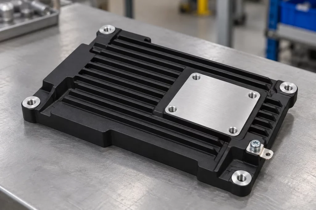
| Feature | Coating risk | Drawing or process control |
| Fits and threads | Film build reduces clearance and can obstruct engagement. | Mask, allow for the finish, or approve controlled post-coat machining. |
| Grounding points | The organic film can interrupt metal-to-metal electrical contact. | Mark bonding pads and define continuity or resistance verification. |
| Thermal interfaces | The coating and any trapped air can add resistance at a contact joint. | Keep direct-contact pads bare when required and define flatness, pressure, and interface material. |
| Sealing and datums | Build-up or an uneven mask edge can change seating and measurement references. | State whether dimensions apply before or after coating and locate mask boundaries. |
Fits and Threaded Features
Check each fit against its mating component and the finished-state tolerance. The same feature-level reasoning used for CNC machining tolerances applies after coating. Thread masks must protect the required diameter, lead-in, and usable depth. Forcing a screw through cured powder is not a controlled acceptance method because it can damage the finish and leave debris in the assembly.
Grounding and Thermal Contact
A designated grounding pad needs a clean boundary, a suitable fastener interface, and a defined verification method. Bare aluminum may also need a compatible protection strategy that preserves conductivity. For heat-transfer pads, evaluate coating together with contact area, surface flatness, clamping pressure, and any thermal interface material. A sample should be tested under representative heat load when temperature performance is critical.
Coordinate CNC Machining and Powder Coating as One Route
The safest sequence is established before chips are cut. Treat masking, finishing, and final inspection as part of the manufacturing plan rather than instructions added after machining.
- Review the current drawing, aluminum grade or approved alternative, functional interfaces, cosmetic zones, and operating environment.
- Machine the housing with any agreed allowance for surfaces controlled in the finished state; deburr edges without altering critical geometry.
- Clean and pretreat the part using a route compatible with the alloy, contamination condition, and specified coating system.
- Install plugs, caps, or high-temperature masking at the defined boundaries, then verify mask seating before spraying.
- Apply and cure the coating, remove masks cleanly, and inspect boundaries for lifting, chips, or unintended coverage.
- Complete only approved secondary machining or thread restoration, then clean the part and protect newly exposed aluminum as required.
An integrated review can connect the company’s precision machining capabilities with its powder coating service. The exact masking materials, post-coat operations, and inspection methods should still be confirmed for the part.
Verify the First Article Before Production
A first article should prove more than color and appearance. Use the actual mating components or representative gauges where possible, and record the drawing revision and coating specification used for approval.
- Dimensions: measure critical fits, datums, hole locations, and flatness in the state specified on the drawing.
- Assembly: install fasteners, covers, seals, rails, connectors, and locating features without forcing or finish damage.
- Electrical function: verify required bonding or shielding continuity at the specified contact points.
- Thermal function: check temperature performance under a representative load when the housing forms part of the heat path.
- Finish: inspect coverage, cure evidence, mask edges, handling damage, and cosmetic acceptance against an agreed reference.
Record nonconforming features separately. A part should not pass because its exterior looks uniform when a thread, bonding pad, thermal interface, or locating surface fails its own requirement.
What to Put in the Drawing and RFQ
Submit the 2D drawing and 3D model with material, quantity, coating system or performance requirement, color and texture, finished-state dimensions, no-coat zones, mask depth, thread callouts, grounding locations, thermal pads, inspection records, mating-part information, and sample approval criteria. Separate prototype quantity from expected production volume so the supplier can evaluate masking fixtures and process controls appropriately.
Conclusion
CNC-machined aluminum housings can be powder coated successfully when the finish map protects the part’s working interfaces. The design should preserve required clearance, thread engagement, electrical bonding, and thermal contact, while the process plan should connect machining, pretreatment, masking, coating, and finished-state inspection.
FAQs
Should Every Threaded Hole Be Masked
No. Masking depends on thread function, fastener fit, engagement depth, and the approved finishing route. The drawing should identify which threads must remain coating-free and how they will be checked.
Can Powder Coat Be Allowed for in a Close Fit
Sometimes, but the designer and manufacturer must agree on the final clearance and whether the controlling dimension applies before or after coating. Do not rely on a generic film allowance.
Should a Thermal Contact Pad Remain Bare
Often it should when direct metal contact is part of the heat path. Confirm the complete joint, including flatness, contact pressure, interface material, corrosion protection, and the required thermal test.
Is Post Coating Machining Acceptable
It may be, if the operation is planned. Control chips, protect the surrounding finish, re-inspect dimensions, and define how newly exposed aluminum will be handled.
Request a Joint Machining and Coating Review
Send CK Metal Tech the drawing revision, alloy, quantity, mating-part details, coating requirements, no-coat zones, thermal duty, grounding needs, and inspection expectations. Use the request a joint machining and coating review route to confirm the manufacturing sequence before quotation.
One Metal Supplier vs Multiple Vendors: How to Calculate Total Landed Cost
16
October
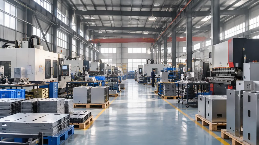
One metal supplier can reduce transfers between fabrication, finishing, and assembly, but supplier consolidation does not automatically lower total landed cost. Compare both routes at the same delivery destination, then add the buyer-side costs needed to turn delivered parts into accepted assemblies. Keep those layers separate: shipping and import charges belong in the landed-cost calculation; supplier administration, inventory, and integration costs belong in the broader sourcing decision.
For an OEM buying custom metal parts, this distinction prevents a lower piece price from hiding extra work. It also avoids calling every future operating expense a landed cost.
Define the Deliverable Before Comparing Vendors
Start with one controlled bill of materials and drawing revision. Specify material, finish, quantity, inspection criteria, packaging, destination, and assembly responsibility. A coated panel from one vendor cannot be compared directly with an assembled enclosure from another unless the missing operations are priced separately.
Distinguish process splitting from dual sourcing. Sending cutting to one shop and coating to another creates sequential handoffs. Qualifying two independent suppliers for the same finished assembly creates a backup route. These arrangements have different costs and continuity benefits; combining them under “multiple vendors” obscures the decision.
Calculate Total Landed Cost in Two Layers
The core shipment calculation is:
Landed cost = supplier invoices + separately charged tooling + packaging + freight + insurance + applicable duties, taxes, and clearance fees.
The International Trade Administration’s landed-cost guidance supports the product-plus-delivery approach. For metal parts, verify which charges are already included in each quotation. Add only costs outside the quoted scope, and use the same receiving location.
Then calculate a separate management metric:
Sourcing comparison cost = landed cost + buyer assembly and inspection + supplier administration + inventory carrying cost + evidence-based quality and disruption allowances.
This second formula is a purchasing decision tool, not a customs valuation or accounting rule. It does not include equipment operating costs over the product’s lifetime. Keep recoverable taxes and other accounting treatments identifiable for finance review rather than treating every cash payment as a permanent expense.
Normalize Quotes and Allocate Shared Charges
Use the same currency, demand period, release size, and named delivery point. Record the delivery term and which party pays each freight leg. A quote that includes shipping can appear expensive beside a factory-gate quote until the missing freight is added.
For international purchases, ask a qualified broker to verify classification, origin, applicable charges, and the relevant shipment date. Do not copy a tariff percentage from another part or last year’s order.
Allocate shared freight across a mixed shipment using a defensible driver, such as chargeable weight or occupied volume. Allocate tooling over the realistically committed program quantity, with tooling ownership shown separately. Show first-order and repeat-order costs independently; an optimistic lifetime volume can conceal a costly launch.
A Worked Example for One Thousand Assemblies
The following figures are hypothetical USD amounts, not CK Metal Tech quotations or tariff estimates. Both routes ultimately provide 1,000 accepted assemblies. The single supplier includes assembly in its invoice; the split route requires more buyer assembly work. Charges already included in supplier invoices are excluded from the other rows.
| Cost category | One supplier | Multiple vendors |
| Supplier invoices | $40,000 | $37,000 |
| Tooling and setup | $3,000 | $2,200 |
| Packaging freight and insurance | $1,800 | $3,300 |
| Illustrative import and clearance charges | $1,500 | $1,500 |
| Core landed cost | $46,300 | $44,000 |
| Buyer assembly and inspection | $800 | $3,300 |
| Supplier administration | $400 | $1,200 |
| Inventory carrying cost | $600 | $1,100 |
| Expected quality and rework allowance | $600 | $1,800 |
| Sourcing comparison total | $48,700 | $51,400 |
| Cost per accepted assembly | $48.70 | $51.40 |
Multiple vendors win the core landed-cost comparison by $2,300. After buyer-side costs are included, one supplier is lower by $2,700. This result follows the stated assumptions; it does not prove that consolidation is generally cheaper.
The decision changes if the split route reduces internal assembly effort, avoids quality losses, or provides a valuable qualified backup. Replace every allowance with program evidence before using this example for an award decision.
Measure Handoffs Without Double Counting
Map the route from cutting and forming through machining, coating, final inspection, and packing. Sheet metal fabrication may involve several linked operations, so track the transfers between them rather than counting suppliers alone.
For each handoff, record transport, protective packaging, receiving inspection, queue time, and revision-control responsibility. Estimate internal work from hours multiplied by an approved labor rate. Distinguish cash savings from staff capacity released: fewer purchase orders do not necessarily reduce payroll.
Estimate inventory carrying cost from average inventory value, the approved annual carrying rate, and the time period. Use historical rework and expedite costs where available. For a new program, show low, expected, and high cases rather than inventing a precise failure probability.
Avoid charging the same loss twice. If rejected units already reduce the accepted-unit denominator, check whether a separate scrap allowance repeats that loss. Likewise, do not add replacement freight when it is already included in a rework estimate.
Choose the Route and Test Its Weak Points
One supplier is attractive when interfaces dominate the program: welded frames must match machined brackets, coating boundaries affect fit, and completed assemblies require a coordinated release. Multiple vendors may be preferable when a process needs specialist qualification, capacity is constrained, or a genuinely independent backup is essential.
A backup is only useful if drawings, tooling access, qualification status, and available capacity make it executable. Two suppliers sharing the same critical subcontractor may still have a common interruption risk. Keep continuity requirements visible beside the cost comparison.
Test the decision against smaller releases, a rejected batch, an engineering change, and an expedited shipment. If the winner changes under a small assumption adjustment, resolve that uncertainty before committing the production route.
Request a Comparable Metal Manufacturing Quote
CK Metal Tech combines sheet metal processing, machining, stamping, powder coating, painting, and precision-component assembly. Review its metal manufacturing and assembly capabilities against the proposed route; process breadth alone does not establish capacity or suitability for a particular program.
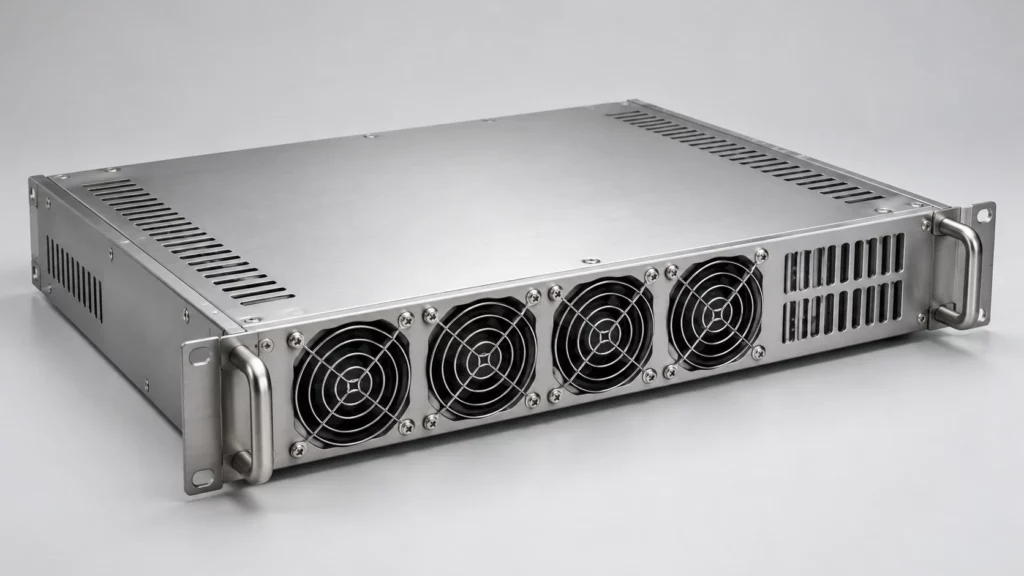
Send the BOM, controlled drawings, quantities, destination, finish requirements, and acceptance plan. Ask CK Metal Tech to separate tooling from recurring prices and identify subcontracted operations, excluded services, and packing assumptions. Give alternative vendors the same package.
Conclusion
Choose the sourcing route using both delivered cost and the work required to obtain accepted assemblies. A transparent comparison can show that multiple vendors win on landed cost while one supplier wins after integration costs, or the reverse. Award the route whose cost assumptions and continuity requirements can be verified.
FAQs
Is one metal supplier always cheaper
No. Consolidation may reduce transfers and administration, while multiple vendors can provide specialist capability or backup capacity. Compare equivalent outputs and documented costs.
Is total landed cost the same as total cost of ownership
No. Landed cost addresses acquisition and delivery. Ownership cost extends into use, maintenance, and disposal. Buyer integration costs should remain a clearly labeled comparison layer.
How should tooling be included
Show the initial tooling payment separately, then allocate it across a defensible committed quantity for the unit comparison. Record ownership, maintenance responsibility, and repeat-order assumptions.
Should supplier management time count as a saving
Include it when comparing resource demand, but distinguish released staff capacity from actual cash savings. Use measured hours and an approved rate.
Request a Sourcing Route Review
Share the current drawings, BOM, delivery location, release schedule, and assembly scope with CK Metal Tech. Request a sourcing-route review to clarify included operations and compare the assumptions behind each quotation.